

ACV 42XFO008-0 Steering Wheel Control Interface Adaptor For Ford
- Stock Status: In Stock
- Item Condition : New
- Available QTY : 5
- Brand: ACV
- Model: 42XFO008-0 / FO008.2
- EAN: 7427307020884
- Warranty: 1 Year Warranty
Description
Steering Wheel Control Interface Adaptor. Connecting to the original radio connector and plugging in to the back of the new head unit is simple to fit.
A stalk/steering wheel control adaptor allows you to upgrade to an aftermarket head unit whilst maintaining use of your factory steering wheel controls or fitted on a stalk next to the steering wheel.
Vehicles with steering wheel OK and/or speech button. Vehicles with OEM display. Vehicles with CD player under the display. vehicles with SYNC: SYNC function not supported
Product Compatibility Chart
| Make | Model | Years | Notes |
| Ford | B-Max | 2012 - 2017 | (JK8) |
| Ford | C-Max | 2010 - 2019 | (DXA) |
| Ford | Eco Sport | 2014 - 2017 | (JK8) |
| Ford | Fiesta | 2013 - 2017 | (JA8/JR8) |
| Ford | Focus | 2011 - 2014 | (DYB) |
| Ford | Kuga | 2013 - 2019 | (DM2) |
| Ford | Ranger | 2011 - 2015 | (2AB) |
| Ford | Taurus | 2008 - 2012 | |
| Ford | Tourneo Custom | 2012 - 2016 | (FAC/FAD) |
| Ford | Transit | 2014 - 2016 | (V363) (FCA/FAD) |
| Ford | Transit Connect | 2013 - 2018 | (PJ2) |
| Ford | Transit Custom | 2012 - 2016 | (FAC/FDA) |
| Ford | Transit Tourneo Connect | 2013 - 2018 | (PJ2) |
Features & Benefits
- Retain Steering Wheel Control Functionality
- Replace Factory Radio
- Outputs For Speed Pulse, Reverse & Park Brake
- Retains Time & Date Settings
- Software Updateable
- Remappable Buttons
Installation Guide
The 42XFO008-0 allows for the retention of the steering wheel controls as well as other vital features when installing an aftermarket unit into the vehicle.This interface features selectable dipswitches for dedicated applications, simply refer to the provided table for the correct configuration ensuring seamless integration.
What's Included
- 42XFO008-0 Steering Control Adaptor
- FREE CTMULTILEAD.2 Stereo Patch Lead
PRIOR TO INSTALLATION
Installation requires a certain level of technical knowledge. Before installation, it is important to read the manual. Select a location for installation that is dry and free from heat sources. It is essential to use the correct tools during installation to prevent any damage to the vehicle or the product itself. Please note that we cannot be held liable for any issues arising from improper installation. Before proceeding with installation, disconnect the negative battery terminal and ensure the key is removed from the ignition.
Wiring Key ISO Connector Wiring Key
- Purple Right Rear Speaker +
- Purple/Black Right Rear Speaker -
- Green Left Rear Speaker +
- Green/Black Left Rear Speaker -
- Grey Right Front Speaker +
- Grey/Black Right Front Speaker -
- White Left Front Speaker +
- White/Black Left Front Speaker -
- Yellow Permanent 12V
- Black Ground
- Red Ignition 12V
- Orange Illumination
Flying Wire Wiring Key
- Pink Speed Pulse - 0 to 12V Square Wave @ 1Hz/Kph
- Green Park Brake
- Purple/White Reverse Gear - 250mA
- Orange Illumination - 250mA
- Red/White Acc 12V - 250mA
- Yellow RCA Camera
Outputs & Ratings
- Standby Current <3mA
- Operating Voltage 6V to 16V
- Operating Temperature -20C to 85C *rated at 25 degrees Centigrade
Dipswitch Configuration
| MANUFACTURER | SYSTEM | DIPSWITCH CONFIGURATION | CONNECTION | |||
| 1 | 2 | 3 | 4 | |||
| RESERVED | NA | OFF | OFF | OFF | OFF | SOFTWARE UPDATE MODE |
| ALPINE | IR DATA | OFF | ON | OFF | OFF | MALE 3.5MM JACK |
| ANALOG SINGLE EXTEND | Analog | ON | ON | ON | ON | BROWN SWC IR |
| ANALOG SINGLE WIRE | Analog | ON | ON | ON | OFF | BROWN SWC IR |
| CLARION | IR DATA | ON | OFF | OFF | ON | MALE 3.5MM JACK |
| CUSTOM | IR DATA | ON | OFF | ON | OFF | HEAD UNIT DEPENDANT |
| GRUNDIG | IR DATA | OFF | ON | OFF | ON | BROWN SWC IR |
| JVC | IR DATA | OFF | OFF | ON | OFF | BROWN SWC IR |
| KENWOOD 1 | IR DATA | ON | OFF | OFF | OFF | BROWN SWC IR |
| KENWOOD 2 | IR DATA | ON | ON | OFF | OFF | BROWN SWC IR |
| KEY 1 / KEY 2 | Analog | OFF | ON | ON | OFF | KEY1 / KEY 2 WIRES |
| KEY 1 / KEY 2 EXTEND | Analog | OFF | ON | ON | ON | KEY1 / KEY 2 WIRES |
| PHILIPS | IR DATA | OFF | ON | OFF | ON | BROWN SWC IR |
| PIONEER 1 | Analog | OFF | OFF | OFF | ON | MALE 3.5MM JACK |
| PIONEER 2 | Analog | OFF | OFF | ON | ON | MALE 3.5MM JACK |
| SONY | Analog | ON | OFF | ON | ON | MALE 3.5MM JACK |
| ZENEC | IR DATA | ON | ON | OFF | ON | BROWN SWC IR |
Dipswitch 5 & 6
Dipswitch 5 & 6 are reserved for vehicle-specific configuration.
| KEY1 and KEY2 | KEY1 and KEY2 are specifically tailored for analog learning mode-style radios. Our SWC module is designed with a resistor chain that precisely matches the required resistance for seamless compatibility with this type of head unit. |
| KEY1 and KEY2 EXTEND | This mode extends every button press to 2 seconds during the learning process. However, with rolly wheel-designed steering wheel buttons, holding for 2 seconds isn’t feasible. Our KEY1 and KEY2 extend features to address this by automatically prolonging each press, simplifying head unit programming even in such scenarios. Extend mode is not intended for normal use, it is only used in the teaching process. |
| ANALOG SINGLE WIRE and ANALOG SINGLE WIRE EXTEND | This function operates similarly to KEY1 and KEY2 but transmits all unique values through the IR SWC single wire. This is crucial for compatibility with learning-style head units featuring only one learning input wire. To ensure compatibility, we’ve incorporated this feature into our steering wheel control interface, ensuring seamless operation across various head unit setups. The Analog Extend mode functions identically to its counterpart within the KEY1 and KEY2 system but transmits through a single wire. |
SWC Interface
Connection Guide Before Installation
- Prior to installing the interface, it is essential to remove and disconnect the factory stereo.
- For guidance on this process, please refer to the vehicle owner’s manual/handbook or seek assistance from a professional.
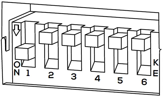
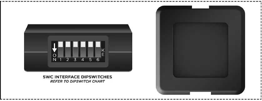
Setting The Dipswitches
- This interface includes a set of dip switches.
- Consult the dipswitch selection guide to select the appropriate configuration.
- To activate a dipswitch, press it downward into the ‘ON’ position.
- Refer to the diagram for an example of the ‘KENWOOD1’ dipswitch configuration.
Installation
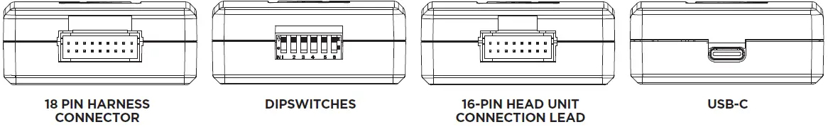
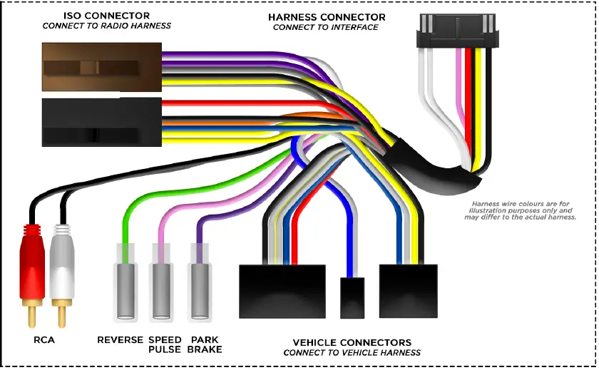
- Take the interface, then connect the 16-PIN head unit connection lead and the 18-PIN steering wheel harness connectors to their respective ports.
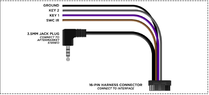
- Connect the head unit connection to the steering wheel remote input on the rear side of the aftermarket stereo. Connection methods vary based on the stereo brand, utilizing either a 3.5mm jack connector SWC IR wire or wired inputs KEY1 and KEY2. For specific connection guidance, refer to your aftermarket stereo’s installation manual if not clearly labeled on the stereo harness.
- Connect the power/speaker ISO connector from the interface to the corresponding power/speaker ISO connection on the aftermarket stereo. For aftermarket stereos lacking an ISO connector, refer to the “Wiring Key” on Page 2 for guidance on connecting wires. Certain interfaces may also include extra “flying” wires for additional functionalities such as parking brake trigger, reverse gear, and speed pulse. Further information on these wires is available in the “Flying Wire Wiring Key” section.
- Connect the vehicle-specific connectors from the interface harness to the corresponding connectors on the vehicle harness.
- Connect the flying wires on the harness to the rear of the stereo (iff applicable).
- Connect the antenna adapter to the vehicle’s existing connection at the rear of the aftermarket stereo.
- When installing an aftermarket reverse camera, connect the yellow RCA from the harness to the yellow RCA of the aftermarket camera. (If supported by the interface and vehicle)
- When installing a DAB antenna, ensure to connect the DAB aerial connector to the rear of the new stereo.
- After connecting all wires (along with any additional accessories), it’s crucial to thoroughly test the stereo and steering wheel controls before reassembling the dashboard. If steering wheel controls are unresponsive, inspect connections and check dipswitch settings. Repeat the connection process if necessary, following the outlined steps.
Steering Wheel Control Configuration
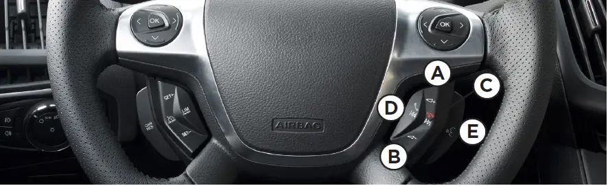
- A Volume Up
- B Volume Down
- C Track Up
- D Track Down
- E Mute
The provided diagram, while meticulously researched, serves as an example only. Actual steering wheel control configurations may vary depending on each vehicle. SETTING THE TIME & DATE
- Press the Speech button to turn on the vehicle display.
- Press and hold the Speech button for two seconds to enter the menu mode.
- Use the Volume + / - buttons to navigate to the “Clock Settings” menu and press Speech to select it.
- Adjust the time by using the Volume + / - buttons, then press Speech to confirm.
- Repeat the process to set the date.
- Once the time and date are set, press Speech to save the settings.
The menu will automatically exit after 10 seconds of inactivity.
Connection Diagram Head Unit Connection Lead
SWC Interface
SWC Vehicle Harness
Car Audio Fitting Accessories are sold with limited instructions. Some knowledge of car audio installation is helpful, as in some rare case "modification" is necessary.
Please make sure that is the correct Steering Control Adaptor for your vehicle by firstly checking to see if your vehicle make, model and year is listed in the description. Secondly by checking to see if the connection in the picture listed is the same as you have in your vehicle. If in doubt please email us with your vehicle details and we will confirm what you require.
