The brackets supplied in the above kits will only line up with the original top mount locator. In cases where the bottom does not line up you will need to make a new pilot hole to screw
the bottom as shown in the photo.
 
The Canbus Harness adapter you have has a blue wire with a male bullet connector.
 
This requires a connection from your new stereo to turn on the amplifier within the vehicle.
 
The wire colours differ slightly from stereo to stereo but are generally either blue in colour or blue with a white tracer as in the photos below.
 
The antenna adapter also has a blue wire that requires a connection to the same remote wire from the stereo harness.
 
If a remote wire is not present on your brand of stereo you can take a spurred feed from the red wire on the adapter harness.


Many CAN BUS adapters come with additional output wires as in the photo below.
 
They are used for various stereo installations such as installing a reverse camera.
 
A description for what each one is below:
 

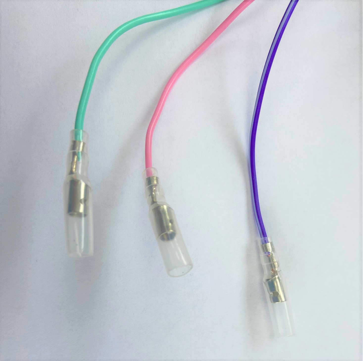
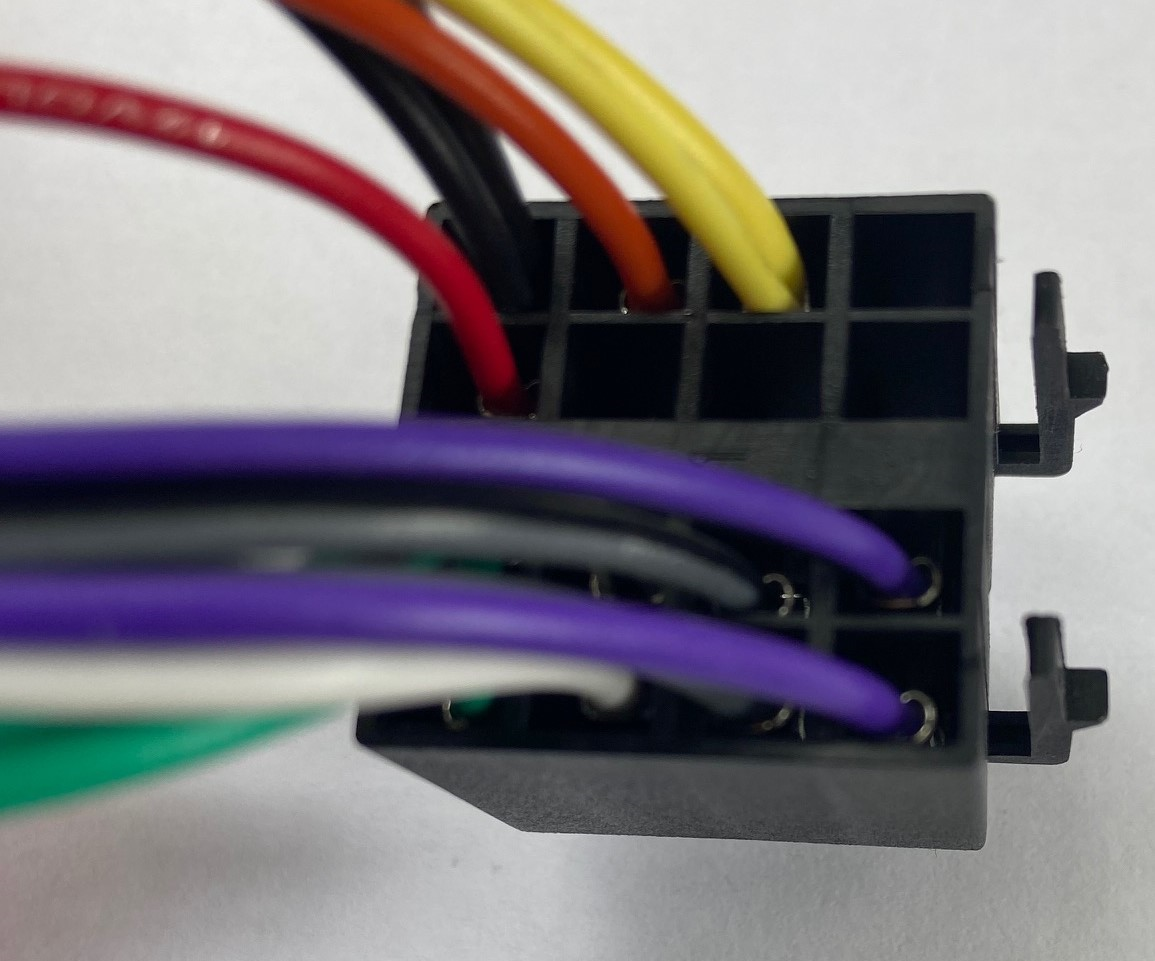
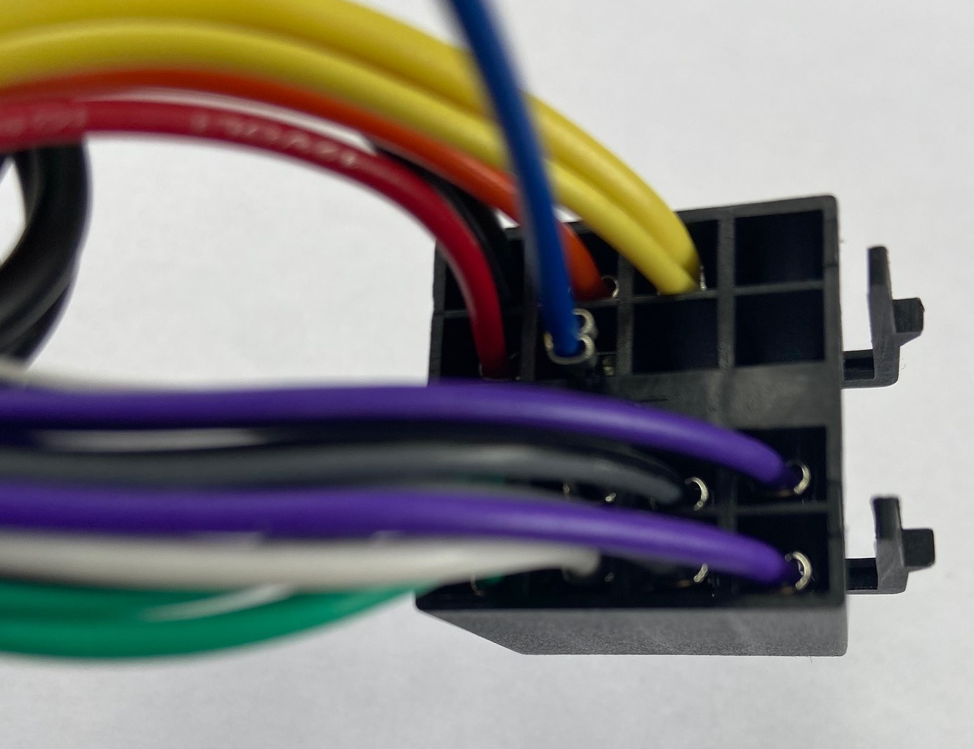
What is the PINK wire?

The Pink wire is a speed pulse output. Some stereos / navigation systems have a speed pulse wire and this tells the new stereo how fast or slow the vehicle is travelling.
Not all new stereos have this nowadays.
 

What is the GREEN wire?

The Green wire is simply a handbrake wire which sends a negative signal to the stereo to tell the stereo that the parking brake is applied or released.
This is a safety device to stop certain menus on the stereo being used on the move.
This wire is always found on Touchscreen AV units mainly.
 

What is the PURPLE – WHITE wire?

The Purple – white wire is simply a reverse gear output. This is used when installing a reverse camera to trigger the reverse wire signal on the new stereo also normally the same colour.
When connected when reverse gear is engaged the stereo will automatically switch to reverse channel.
 
PLEASE NOTE, NOT ALL VEHICLE CAN BUS SYSTEMS SUPPORT THESE OUTPUTS. VERY RARELY SOME VEHICLES MAY NOT BE FULLy COMPATIBLE WITH ALL OUTPUTS.
Many stereos have a direct ISO socket on the rear of the stereo now.
 
These stereos tend to not come with any ISO harness adapter also.
 
When using an adapter they do not always supply a remote output feed and the location is empty.
 
In the photo below the space directly under the orange wire location is the remote output terminal:
 
With a suitable terminal this can be added to give a remote output for amplifiers and powered antennas.
 

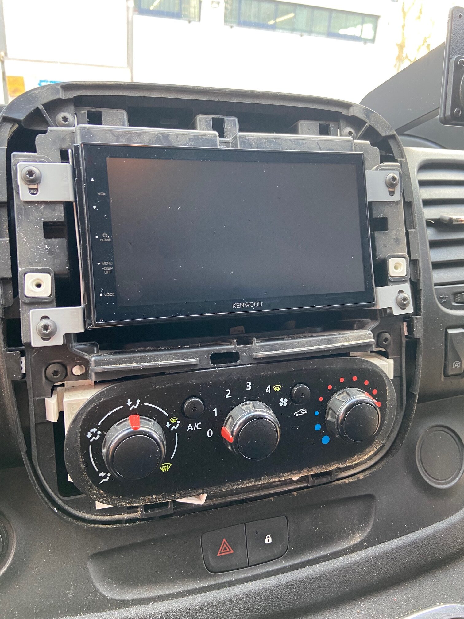
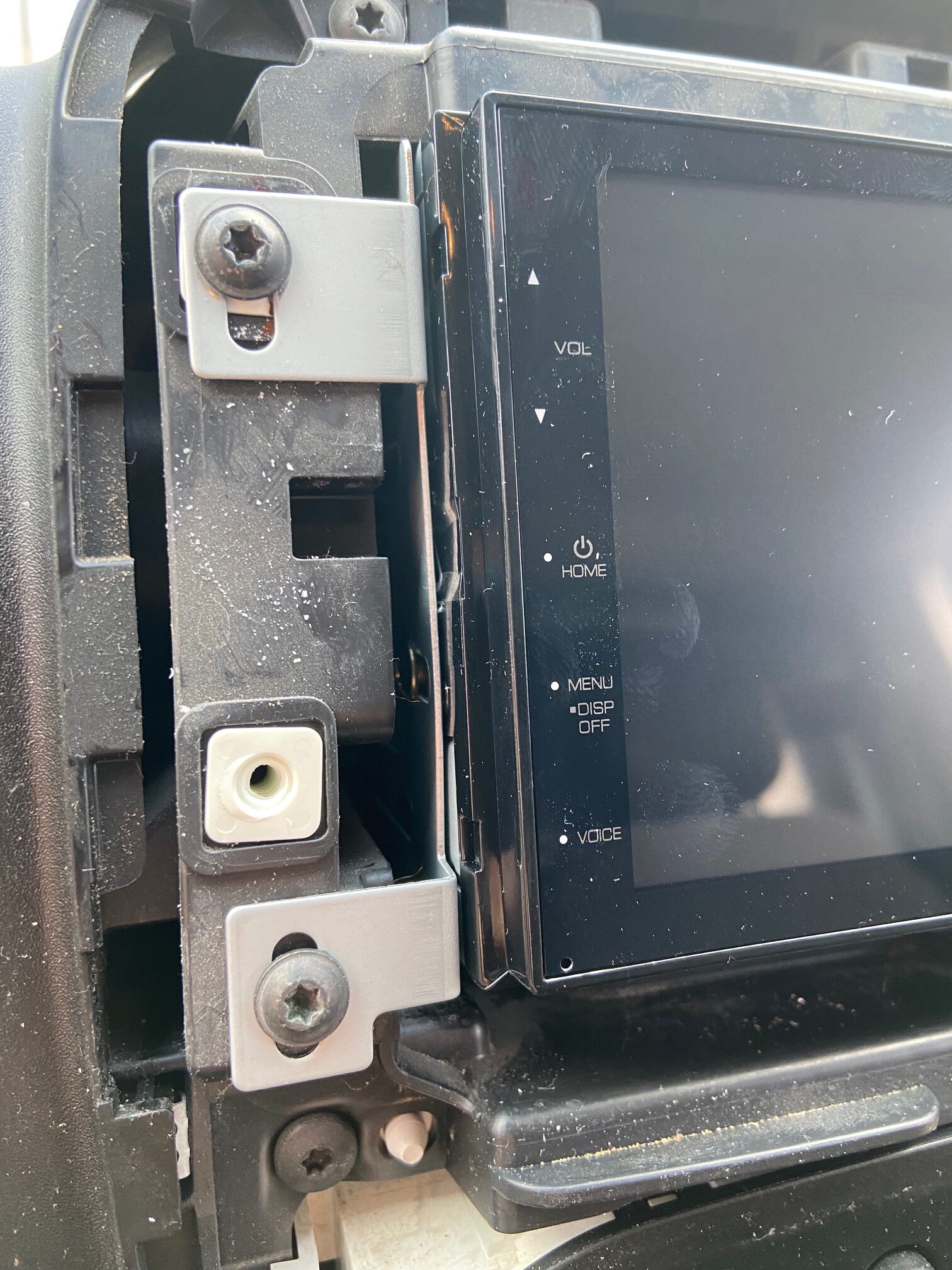
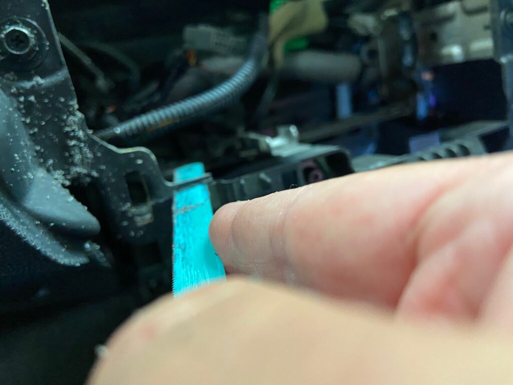
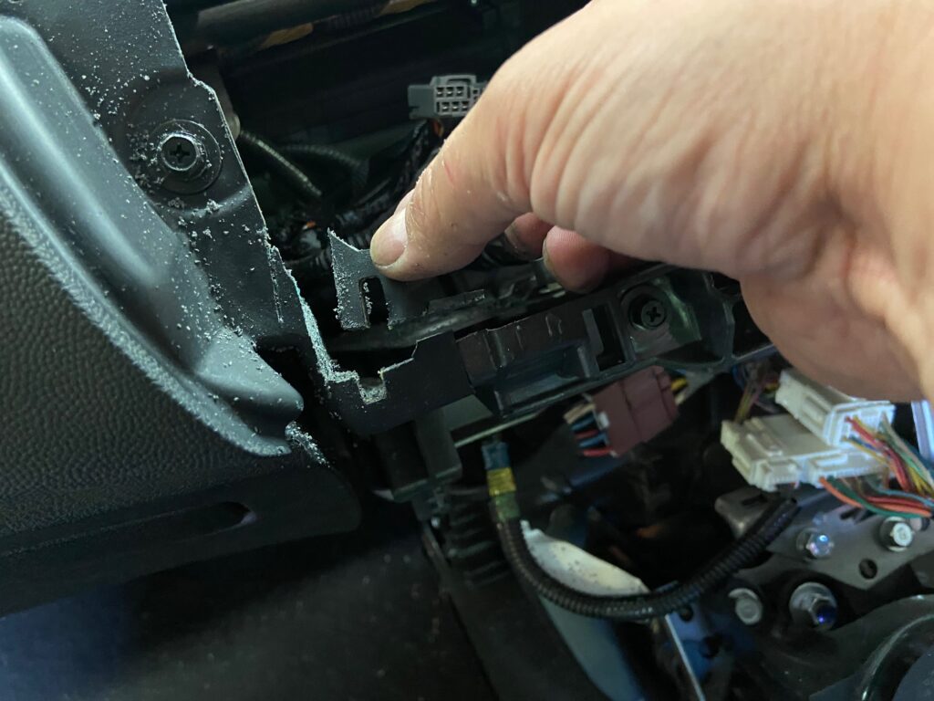
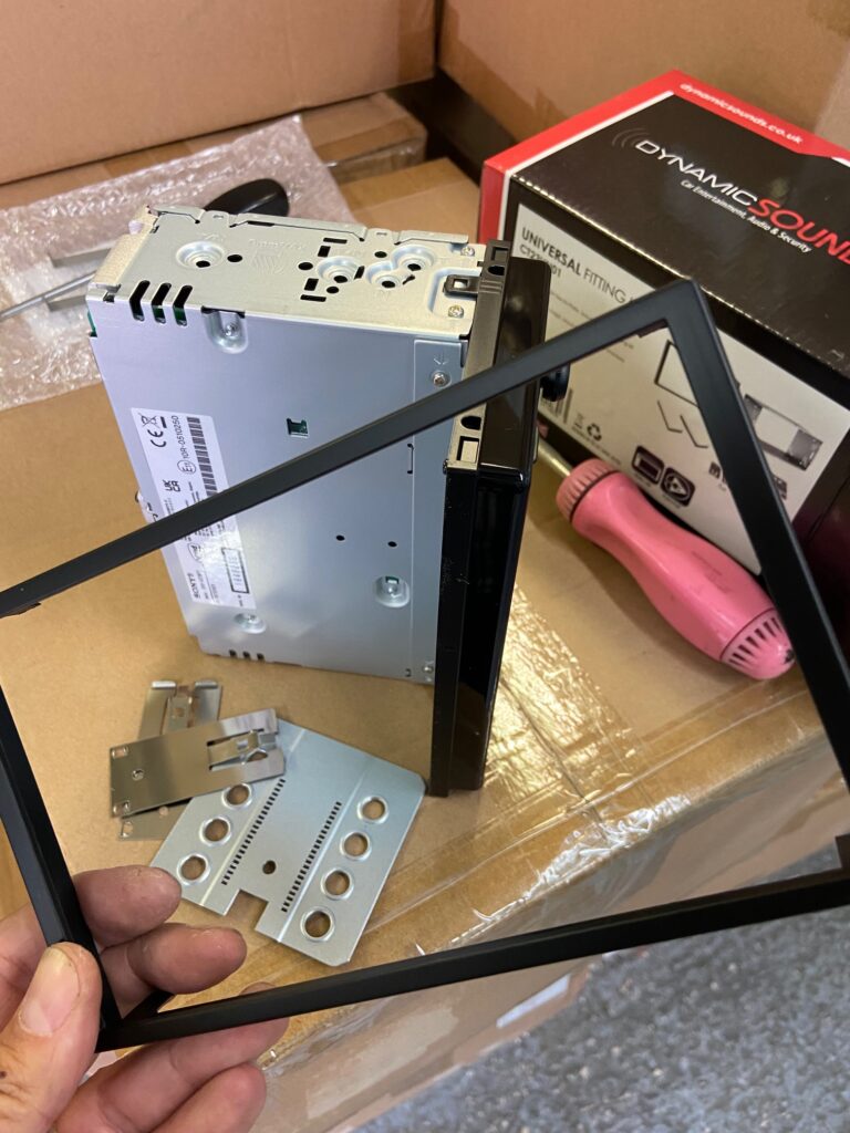
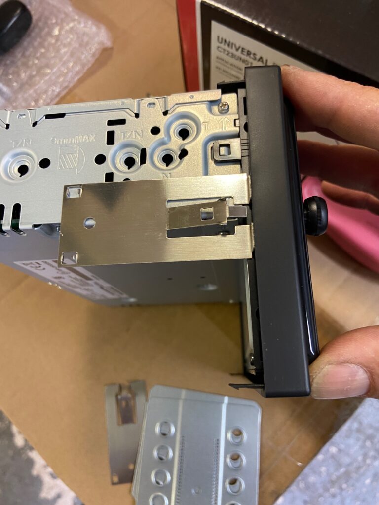
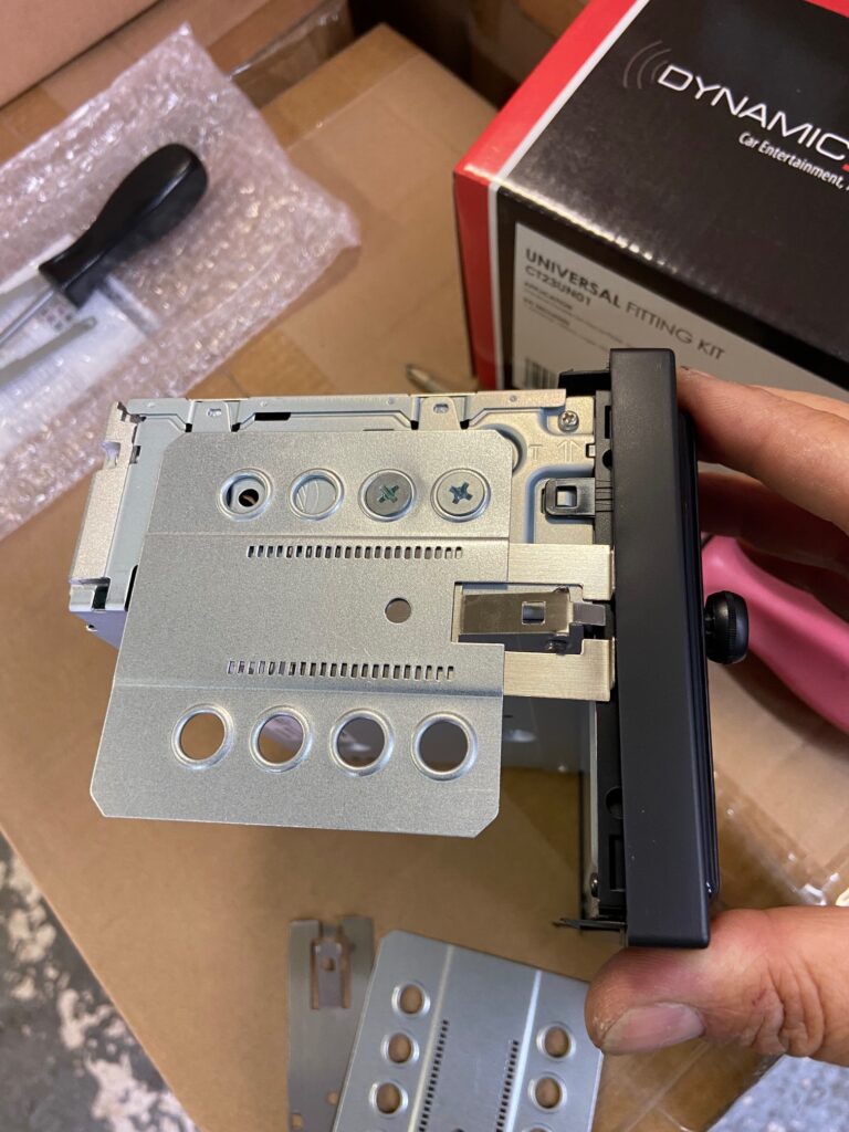
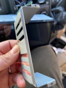
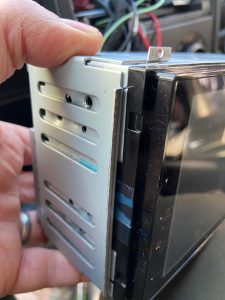
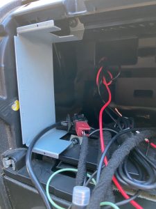
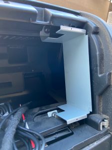
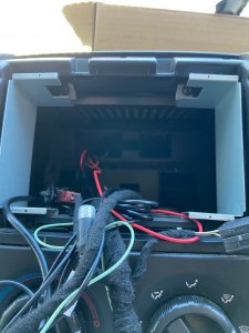
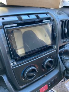
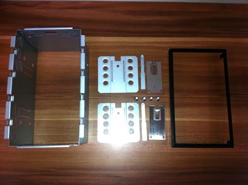
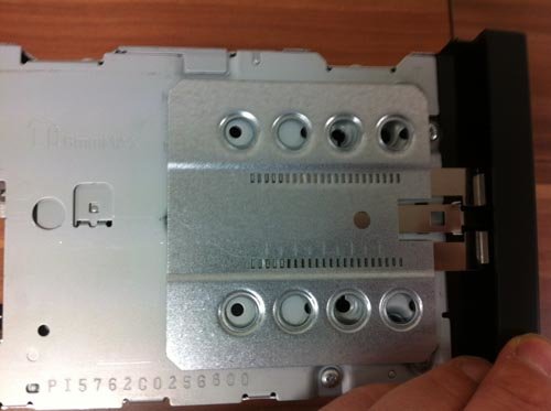
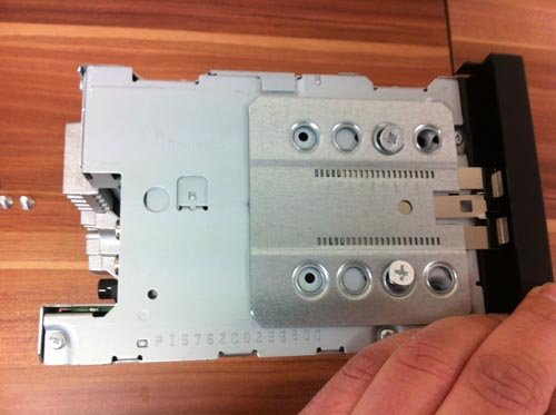
Some Trimming of internal plastic of the dash may be required for this bracket to sit in its final position.

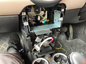
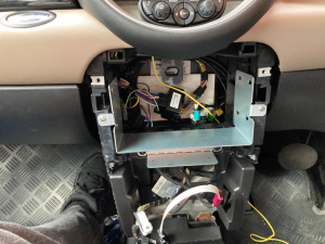
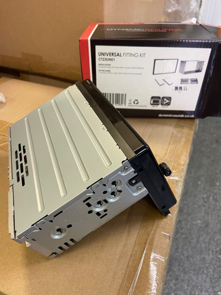
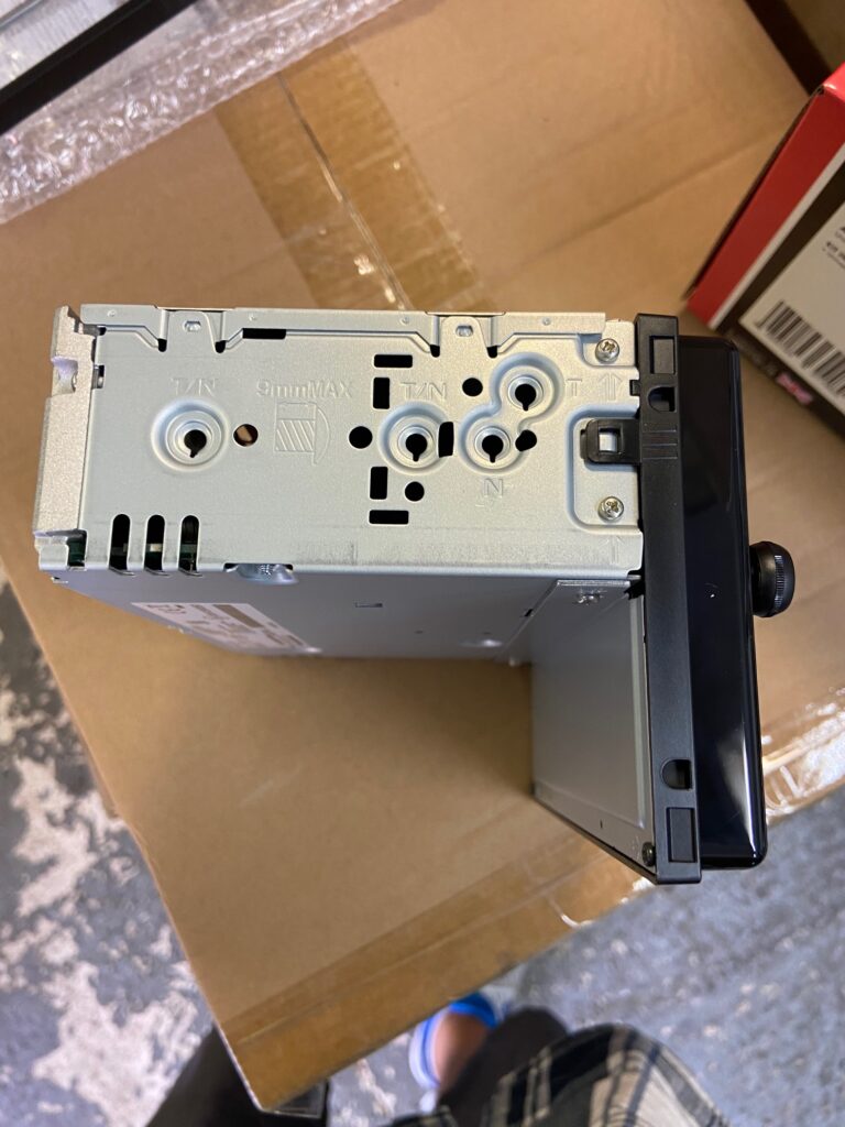
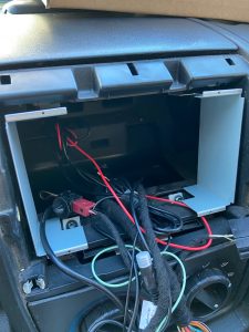
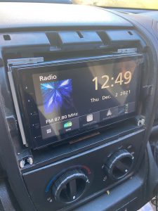
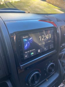
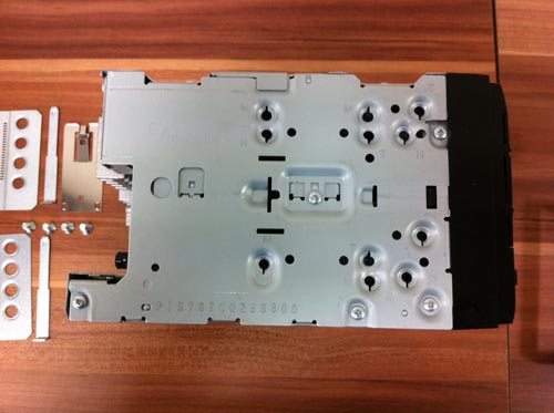
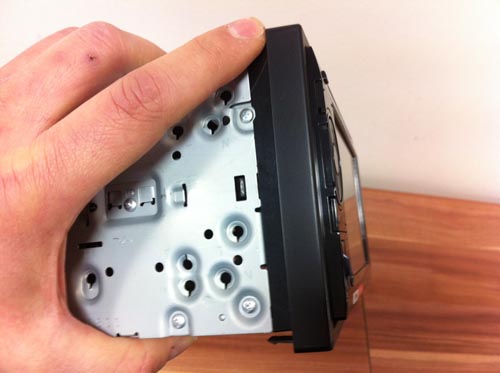
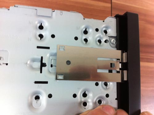
Please follow pics 1 to 6 as this a step by step guide on how to mount the brackets on your double din unit.

Your new stereo will require 3 supplies to switch on

  1. Ignition live 12v+ red wire on stereo
  2. Permanent live 12v+ yellow wire on stereo
  3. Earth/ground 12v- black wire on stereo
  • If all these wires are NOT connected then the unit will NOT switch on.
  • With the help of a multimeter check to see if you have power at these points.
  • Some cars are not equipped with an ignition supply and this is the most common reason for the unit not to switch on. In this case a wire will need to be sourced from another point in the vehicle and connected to the red wire of the stereo harness.
  • If there is an ignition wire present, but still no power then check the fuses in the fuse box to make sure that they are not blown.

Most common vehicle with no accessory or ignition live : ALFA ROMEO, AUDI, FIAT, MERCEDES AND VW.

  • Simply pick out the yellow wire and the red wire from the stereo wiring harness
  • Midway down you can unplug them
  • Connect yellow to red and then red to yellow
  • Your stereo wiring will be now configured correctly to match the vehicles configuration

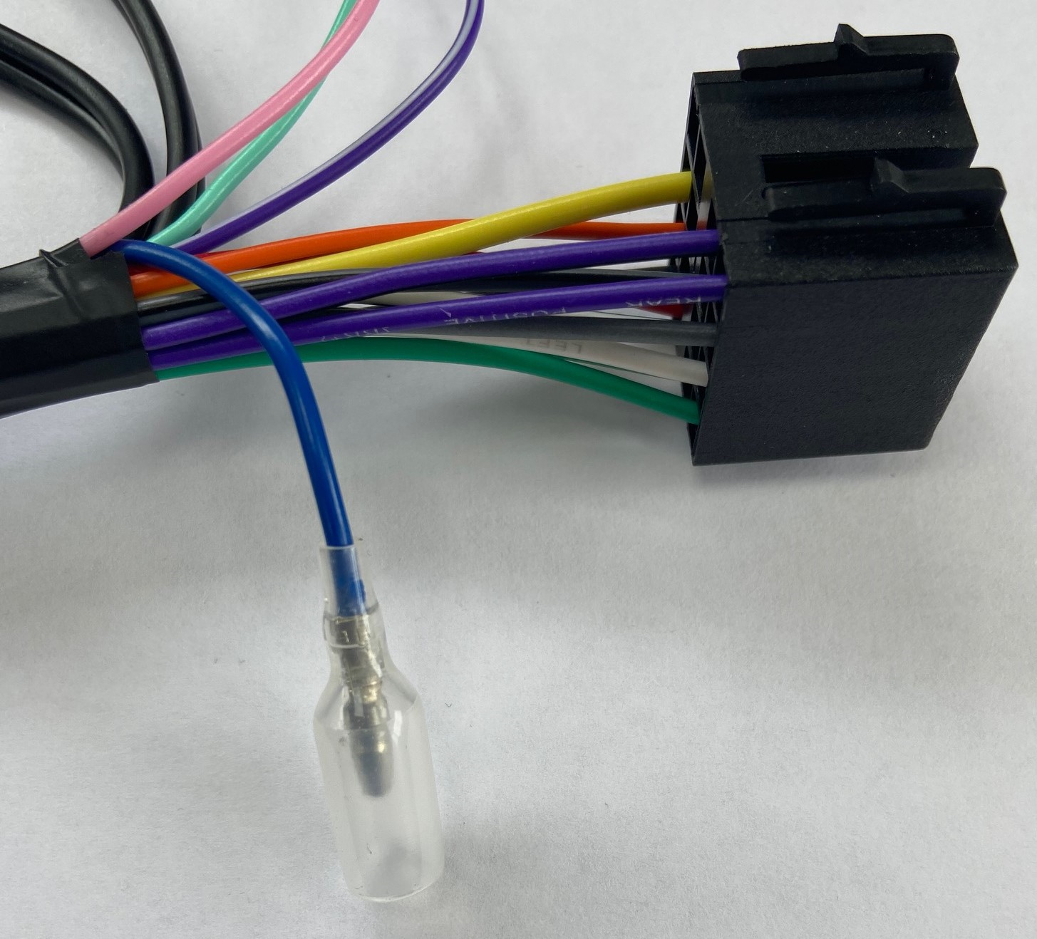
Your Kenwood stereo will have two available options to connect the patch lead to the stereo

Round 4 pin plug

Single wire input – colour : blue with yellow stripe
You can only use what is required by the stereo.

For Connects2 patch leads the single wire will be brown with a red bullet connector on the end
For Autoleads patch leads the single wire will be blue.

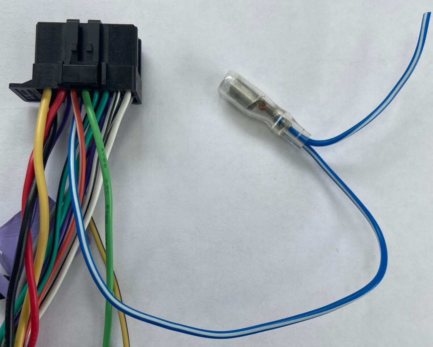
Your JVC stereo will have two available options to connect the patch lead to the stereo

Jack plug

Single wire input – colour : blue with yellow stripe

You can only use what is required by the stereo.

For Connects2 patch leads the single wire will be brown with a red bullet connector on the end

For Autoleads patch leads the single wire will be blue

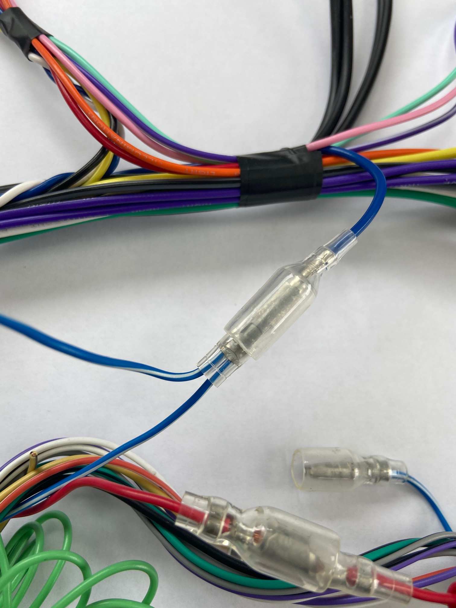
  1. Connect this to the remote antenna output wire or the amp remote wire from your car stereo (this is normally blue in color or blue/white)
  2. If no remote wire is present then connect to an accessory supply or ignition driven supply instead.


YouTube player